Technical Parameters
Transmitter Usage
1. Detection principle: This system through standard DC 24V power supply, real-time display and output standard 4-20mA current signal, analysis and processing to complete digital display and alarm operation. 2. Applicable objects: This system supports the standard sensor input signals. Table 1 is our gas parameters setting table (For reference only, users can set the parameters according to the needs) Table 1 Conventional gas parameters| Detected gas | Measure Range | Resolution | Low/High Alarm Point |
| EX | 0-100%lel | 1%lel | 25%lel /50%lel |
| O2 | 0-30%vol | 0.1%vol | <18%vol, >23%vol |
| N2 | 70-100%vol | 0.1%vol | >82%vol, <90%vol |
| H2S | 0-200ppm | 1ppm | 5ppm /10ppm |
| CO | 0-1000ppm | 1ppm | 50ppm /150ppm |
| CO2 | 0-50000ppm | 1ppm | 2000ppm /5000ppm |
| NO | 0-250ppm | 1ppm | 10ppm /20ppm |
| NO2 | 0-20ppm | 1ppm | 5ppm /10ppm |
| SO2 | 0-100ppm | 1ppm | 1ppm /5ppm |
| CL2 | 0-20ppm | 1ppm | 2ppm /4ppm |
| H2 | 0-1000ppm | 1ppm | 35ppm / 70ppm |
| NH3 | 0-200ppm | 1ppm | 35ppm / 70ppm |
| PH3 | 0-20ppm | 1ppm | 1ppm / 2ppm |
| HCL | 0-20ppm | 1ppm | 2ppm /4ppm |
| O3 | 0-50ppm | 1ppm | 2ppm /4ppm |
| CH2O | 0-100ppm | 1ppm | 5ppm /10ppm |
| HF | 0-10ppm | 1ppm | 5ppm /10ppm |
| VOC | 0-100ppm | 1ppm | 10ppm /20ppm |
Wiring instructions
The internal wiring of the instrument is divided into display panel (upper panel) and bottom panel (lower panel). Users only need to connect the wiring on the bottom plate correctly. Figure 2 is the diagram of the transmitter wiring board. There are three groups of wiring terminals, power communication interface, alarm lamp interface and relay interface.Display transmitter's factory appearance is like figure 1, there has mounting holes on the transmitter rear panel. The user only need to connect line and other actuator with the corresponding port according to the manual, and connect DC24V power, then it can work.
Functional operation instructions
5.1 Panel description As shown in Figure 5, The transmitter panel is composed of a concentration indicator, a digital tube, a status indicator lamp, a first class alarm indicator lamp, a two level alarm indicator lamp and 5 keys. This diagram shows the studs between the panel and the bezel, After removing the bezel, observe the 5 buttons on the panel. Under normal monitoring condition, the status indicator flashes and the digital tube shows the current measurement value. If the alarm situation occurs, the alarm light indicates level 1 or 2 alarm, and the relay will attract.Figure 1 Appearance
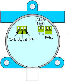
Figure 2 Internal structure
Client interface connection: (1)Power signal interface: "GND", "Signal" , "+24V". The signal export 4-20 mA 4-20mA transmitter wiring is like figure 3.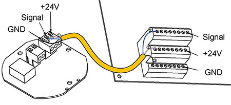
Figure 3 Wiring illustration
Note: For illustration only, the terminal sequence is not consistent with the actual equipment. (2)Relay interface: provide a passive switch export, always open, alarm relay pull up. Use as needed.Maximum support 3A/250V. Relay wiring is like figure 4.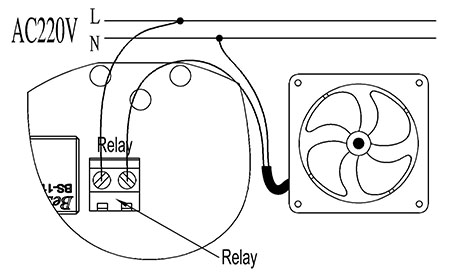
Figure 4 Relay wiring
Notice: It is need to connect AC contactor if user connect big power control device.

Figure 5 Panel
5.2 User instructions 1. Operation procedure Set parameters First step: Press the settings button, and the system displays 0000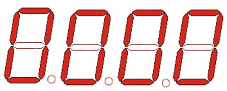 Second steps: Input password (1111 is password). The up or down button allows you to select between 0 and 9 bits, press the settings button to select the next one in turn, Then, select the numbers by using the "up" button Third steps: After input password, press the "OK" button, if the password is correct then the system will enter the function menu, digital tube display F-01, through the "turn on" key to select the function of F-01 to F-06, all the functions in the function table 2. For example, after selecting the function item F-01, press the "OK" button, and then enter the first level alarm setting, and the user can set the alarm at the first level. When the setting is complete, press the OK key, and the system will display F-01. If you want to continue setting, repeat the above steps, or you can press the return key to exit this setting. The function is shown in table 2: Table 2 Function description
 | Function | Instruction | Note |
| F-01 | Primary alarm value | R/W |
| F-02 | Second alarm value | R/W |
| F-03 | Range | R |
| F-04 | Resolution ratio | R |
| F-05 | Unit | R |
| F-06 | Gas type | R |
 ● F-05 Unit settings(Only read) P is ppm, L is %LEL, and U is %vol.
 ● F-06 Gas type(Only read) Digital Tube Display CO2 3. Error code description ● E-01 Over full scale 5.3 User operation Precautions In the process, the user will set the parameters, 30 seconds without pressing any key, the system will exit the environment of setting parameters, back to the detection mode. Note: This transmitter does not support calibration operation. 6. Common faults and handling methods (1) System no response after power is applied. Solution: Check whether the system has electricity. (2) Gas stable display value is beating. Solution: Check if the sensor connector is loose. (3) If you find the digital display is not normal, turn off the power a few seconds later, then turn on.
Important point
1. Before using the instrument, please read the manual carefully. 2. The instrument must be operated in accordance with the rules specified in the instructions. 3. The maintenance of the equipment and the replacement of parts is responsible for our company or around the repair station. 4. If the user does not follow the above instructions without authorization to start repairing or replacing parts, the reliability of the instrument is responsible for the operator. The use of the instrument should also comply with the relevant domestic departments and factories within the instrument management laws and regulations.